Physics 434, 2012: Lecture 16
Back to the main Teaching page.
Back to Physics 434, 2012: Information Processing in Biology. We are proceeding with the dynamical information processing block. In the next couple of lectures, we will follow the article by Detwiler et al., 2000.
Main lecture
- We follow Detwiler et al., 2000, article in this lecture.
- We discussed the basic structure of the vertebrate eye, which consists of rods and cones. We will return to the rods, and their unbelievable ability to detect single photons, in one of the later lectures.
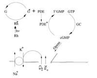
- Crudely, signaling in vertebrate cones can be summarized by the following Fig. 2 of Detwiler et al., see figure on the right.
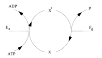
- Notice the number of signaling elements known as futile cycles or push-pull enzymatic amplifiers in this system, see figure to the right. Why are these signaling elements so common in eukaryotic systems?
- We start with the kinetic description of such enzymatic amplifier: Failed to parse (MathML with SVG or PNG fallback (recommended for modern browsers and accessibility tools): Invalid response ("Math extension cannot connect to Restbase.") from server "https://wikimedia.org/api/rest_v1/":): {\displaystyle \frac{dX^*}{dt}=F-G=\frac{k_a E_aX}{1+X/K_a}-\frac{k_d E_dX^*}{1+X/K_d}} . Notice that we use slightly different notation compared to the previous lecture.
- Let's assume now that all enzymes are unsaturated, so that Failed to parse (MathML with SVG or PNG fallback (recommended for modern browsers and accessibility tools): Invalid response ("Math extension cannot connect to Restbase.") from server "https://wikimedia.org/api/rest_v1/":): {\displaystyle \frac{dX^*}{dt}\approx k_aE_aX-k_dE_dX^*} .
- We can now apply the steady state assumption and set: Failed to parse (MathML with SVG or PNG fallback (recommended for modern browsers and accessibility tools): Invalid response ("Math extension cannot connect to Restbase.") from server "https://wikimedia.org/api/rest_v1/":): {\displaystyle \frac{dX^*}{dt}\approx k_a\bar{E_a}\bar{X}-k_d\bar{E_d}\bar{X^*}=0} . Here the overbar means the value averaged over long times. We further recall that Failed to parse (MathML with SVG or PNG fallback (recommended for modern browsers and accessibility tools): Invalid response ("Math extension cannot connect to Restbase.") from server "https://wikimedia.org/api/rest_v1/":): {\displaystyle X^*+X=X_{\rm tot}} . This gives us Failed to parse (MathML with SVG or PNG fallback (recommended for modern browsers and accessibility tools): Invalid response ("Math extension cannot connect to Restbase.") from server "https://wikimedia.org/api/rest_v1/":): {\displaystyle \bar{X^*}\approx \frac{k_a\bar{E_a}X_{\rm tot}}{k_a\bar{E_a}+k_d\bar{E_d}}.}
- Recall that the input signal here is Failed to parse (MathML with SVG or PNG fallback (recommended for modern browsers and accessibility tools): Invalid response ("Math extension cannot connect to Restbase.") from server "https://wikimedia.org/api/rest_v1/":): {\displaystyle E_a} and the output is Failed to parse (MathML with SVG or PNG fallback (recommended for modern browsers and accessibility tools): Invalid response ("Math extension cannot connect to Restbase.") from server "https://wikimedia.org/api/rest_v1/":): {\displaystyle X^*} . The form of the relation between the two indicated above is clearly the usual Michaelis-Menten curve.
- Note that each activation-deactivation cycle consumes energy, and there are Failed to parse (MathML with SVG or PNG fallback (recommended for modern browsers and accessibility tools): Invalid response ("Math extension cannot connect to Restbase.") from server "https://wikimedia.org/api/rest_v1/":): {\displaystyle k_a\bar{E_a}\bar{X}} such cycles per unit time. Thus even at the steady state the system is not stationary and keeps on recirculating Failed to parse (MathML with SVG or PNG fallback (recommended for modern browsers and accessibility tools): Invalid response ("Math extension cannot connect to Restbase.") from server "https://wikimedia.org/api/rest_v1/":): {\displaystyle X} , consuming energy. Why would this structure then be useful instead of a simpler arrangement, where Failed to parse (MathML with SVG or PNG fallback (recommended for modern browsers and accessibility tools): Invalid response ("Math extension cannot connect to Restbase.") from server "https://wikimedia.org/api/rest_v1/":): {\displaystyle X} is produced on demand? Activating a product is typically much faster than producing it, and hence the futile cycle can respond to a changing stimulus much quicker than the time that would be needed to transcribe and then translate the protein. Another reason is that this futile cycle structure is very tunable, as we will see below.
- Now suppose Failed to parse (MathML with SVG or PNG fallback (recommended for modern browsers and accessibility tools): Invalid response ("Math extension cannot connect to Restbase.") from server "https://wikimedia.org/api/rest_v1/":): {\displaystyle E_a=\bar{E}_a+\Delta E_a}
and Failed to parse (MathML with SVG or PNG fallback (recommended for modern browsers and accessibility tools): Invalid response ("Math extension cannot connect to Restbase.") from server "https://wikimedia.org/api/rest_v1/":): {\displaystyle X^*=\bar{X}^*+\Delta X^*}
. For simplicity, we assume that Failed to parse (MathML with SVG or PNG fallback (recommended for modern browsers and accessibility tools): Invalid response ("Math extension cannot connect to Restbase.") from server "https://wikimedia.org/api/rest_v1/":): {\displaystyle E_d={\rm const}}
. We can now expand our equations to the first order in fluctuations of the signal and the response.
- Failed to parse (MathML with SVG or PNG fallback (recommended for modern browsers and accessibility tools): Invalid response ("Math extension cannot connect to Restbase.") from server "https://wikimedia.org/api/rest_v1/":): {\displaystyle \frac{d\bar{X}^*}{dt}+\frac{d\Delta X^*}{dt}=F(\bar{X}^*,\bar{E}_a)-G(\bar{X}^*,\bar{E}_a) +\frac{\partial F(\bar{X}^*,\bar{E}_a)}{\partial X^*}\Delta X^*+\frac{\partial F(\bar{X}^*,\bar{E}_a)}{\partial E_a}\Delta E_a+ \frac{\partial G(\bar{X}^*,\bar{E}_a)}{\partial X^*}\Delta X^*+\frac{\partial G(\bar{X}^*,\bar{E}_a)}{\partial E_a}\Delta E_a}
- This results in Failed to parse (MathML with SVG or PNG fallback (recommended for modern browsers and accessibility tools): Invalid response ("Math extension cannot connect to Restbase.") from server "https://wikimedia.org/api/rest_v1/":): {\displaystyle \frac{d\Delta X^*}{dt}=\frac{1}{\tau}\left(\Delta X^* -g_0 \Delta E_a\right)} , where Failed to parse (MathML with SVG or PNG fallback (recommended for modern browsers and accessibility tools): Invalid response ("Math extension cannot connect to Restbase.") from server "https://wikimedia.org/api/rest_v1/":): {\displaystyle \tau=\left(k_a \bar{E}_a +k_d \bar{E}_d\right)^{-1}} , and Failed to parse (MathML with SVG or PNG fallback (recommended for modern browsers and accessibility tools): Invalid response ("Math extension cannot connect to Restbase.") from server "https://wikimedia.org/api/rest_v1/":): {\displaystyle g_0=\tau k_a \bar{X}} .
- From the differential equation description, it is clear that the system acts as a filter: without the signal, the response relaxes to Failed to parse (MathML with SVG or PNG fallback (recommended for modern browsers and accessibility tools): Invalid response ("Math extension cannot connect to Restbase.") from server "https://wikimedia.org/api/rest_v1/":): {\displaystyle \Delta X^*=0} , and a change in the signal causes a delayed response in the output, with a delay of order of Failed to parse (MathML with SVG or PNG fallback (recommended for modern browsers and accessibility tools): Invalid response ("Math extension cannot connect to Restbase.") from server "https://wikimedia.org/api/rest_v1/":): {\displaystyle \tau} . Thus the system smoothes out (filters) the signals to produce the response. Because Failed to parse (MathML with SVG or PNG fallback (recommended for modern browsers and accessibility tools): Invalid response ("Math extension cannot connect to Restbase.") from server "https://wikimedia.org/api/rest_v1/":): {\displaystyle \tau} defines the delay, Failed to parse (MathML with SVG or PNG fallback (recommended for modern browsers and accessibility tools): Invalid response ("Math extension cannot connect to Restbase.") from server "https://wikimedia.org/api/rest_v1/":): {\displaystyle 1/\tau} is called the bandwidth" -- signals that change on scales faster than that simply "do not go through" the system.
- Notice that if Failed to parse (MathML with SVG or PNG fallback (recommended for modern browsers and accessibility tools): Invalid response ("Math extension cannot connect to Restbase.") from server "https://wikimedia.org/api/rest_v1/":): {\displaystyle \Delta E_a={\rm const}} , then by setting Failed to parse (MathML with SVG or PNG fallback (recommended for modern browsers and accessibility tools): Invalid response ("Math extension cannot connect to Restbase.") from server "https://wikimedia.org/api/rest_v1/":): {\displaystyle d/dt=0} , we calculate the steady state of the system Failed to parse (MathML with SVG or PNG fallback (recommended for modern browsers and accessibility tools): Invalid response ("Math extension cannot connect to Restbase.") from server "https://wikimedia.org/api/rest_v1/":): {\displaystyle \Delta X^*=g_0\Delta E_a} . Thus Failed to parse (MathML with SVG or PNG fallback (recommended for modern browsers and accessibility tools): Invalid response ("Math extension cannot connect to Restbase.") from server "https://wikimedia.org/api/rest_v1/":): {\displaystyle g_0} is called the static gain -- a response of the circuit at the steady state is Failed to parse (MathML with SVG or PNG fallback (recommended for modern browsers and accessibility tools): Invalid response ("Math extension cannot connect to Restbase.") from server "https://wikimedia.org/api/rest_v1/":): {\displaystyle g_0} times the signal.


